R & D – 14. june
We started making another iteration of the first user guide. This this we want to put it on the machine with LED behind that lights up according to the step the user is at.
Started making bill of materials.
F & E and C & F – 14. June
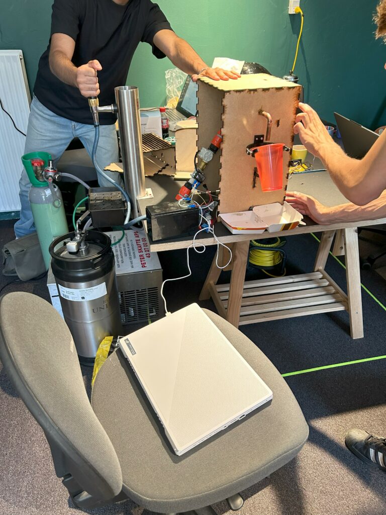
We looked at the systemic composition of the product. All components was inserted into the case/on the frame. This gave some answers to the questions that we wanted to investigate.
- Can the inner components fit?
- There was plenty of room inside the case for the inner components. Although a larger depth of the case could give more room for tubes/hoses to avoid sharp bends.
- Can the inner compontents be installed?
- The installation of the anti-foaming arm fitted perfectly with the cut-out in the case. The start/stop button was also installed correctly with the case hole.
- Will the inner components be protected?
- We determined the the case structure was qualified enough to protect the inner components. Although the current prototype case is made with a material (MDF) and constructed in a way which isnt water proof in any way. Additional testing with a different build would be needed if protection against water leaks should be tested. This part is excluded from our scope of the project.
- Where do we want to mount the components?
- During the test, it was convenient to mount internal hardware components up against the frame inner wall.
- Is the dimensions of the frame correct for usability?
- The frames dimensions are fitted well, but during our test, we found that it was difficult to mount internal components behind the frame. Therefore frame needs to be replaced more into the center of the case, leaving a bit more space to get your hand in behind to mount and secure the components. Alternatively the components should be mounted on the center wall before joining the side walls to the case.
- Will it balance?
- The case was really stable on a table.
- Will it facilitate operation, cleaning, anti-tampering?
- The test of the whole operation is only partially tested, the start/stop button, cup placement, dimensions regarding the eye-level visual aspect was all accepted to be working and reflecting our design brief. Additional factors such as the entire app, physical user manual and anti-tampering was not tested. Further test is needed to validate these factors.
- Are the openings in the case placed in optimal positions and do they have optimal dimensions?
- All openings except the drain hole was approved. Drain hole needs a re-dimensioning
- Can it be mounted?
- Was not tested. But we assume that mounting brackets on the side walls of the case will be no problem to add. This will not be added in this project.
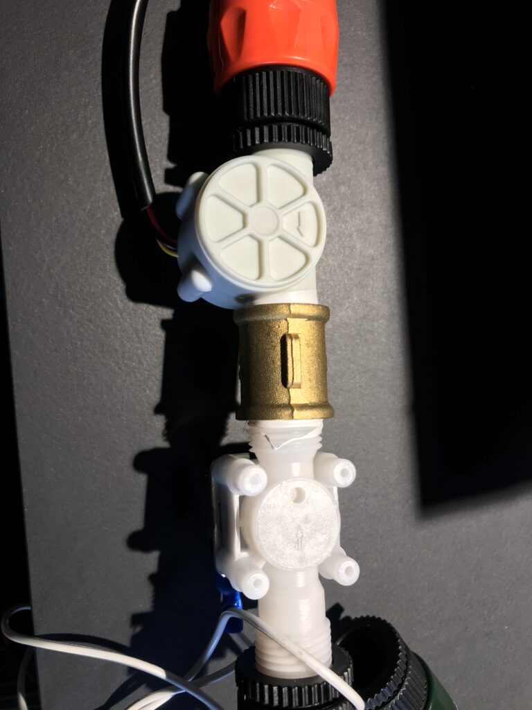
We added a new fittings (screw on clamps) instead of the hose and fittings between the Solonoid Valve and the Flow Sensor. The main thing to test here was the fitting in the case and waterproofness. Both tests was a
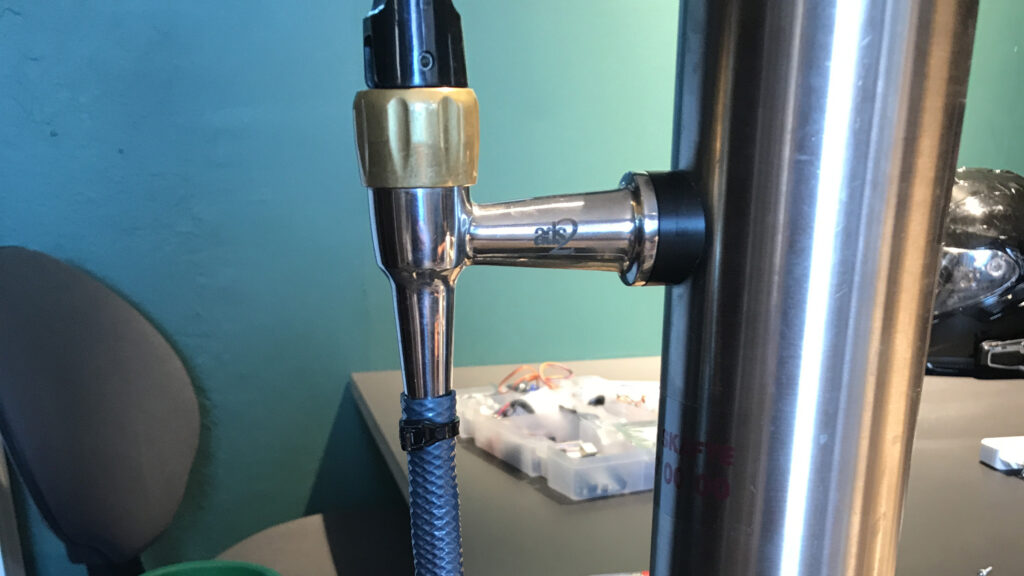
For the testscenario with real beer (and not to risk ruining the borrowed tap beer system) we connected the hose with a strip to the tap of the system.